Flow Control System Block Diagram Block Schematic Of Flow Co
Block diagram of the control flow of system Block diagram system control general generalised Control instrumentation piping drawing flow diagram diagrams symbols ids engineering read learning
System flow block diagram | Download Scientific Diagram
Python control systems library / discussion / open discussion: how to The block diagram of control system for regenerative abs plant Closed loop control system block diagram and working principle
Audit flowchart symbols
Control system systems diagram block loop process closed controller error output examples feedback open negative pid general automatic signal engineeringClosed loop system and closed-loop control systems Flow diagram block chart software professional choose board flowcharting engineeringControl plant regenerative.
System flow block diagramBlock diagram of process control system Diagram block control process system feedback diagrams basics flow figure drawing signals services technologyBlock diagram the proposed system is supposed to maintain a regulated.

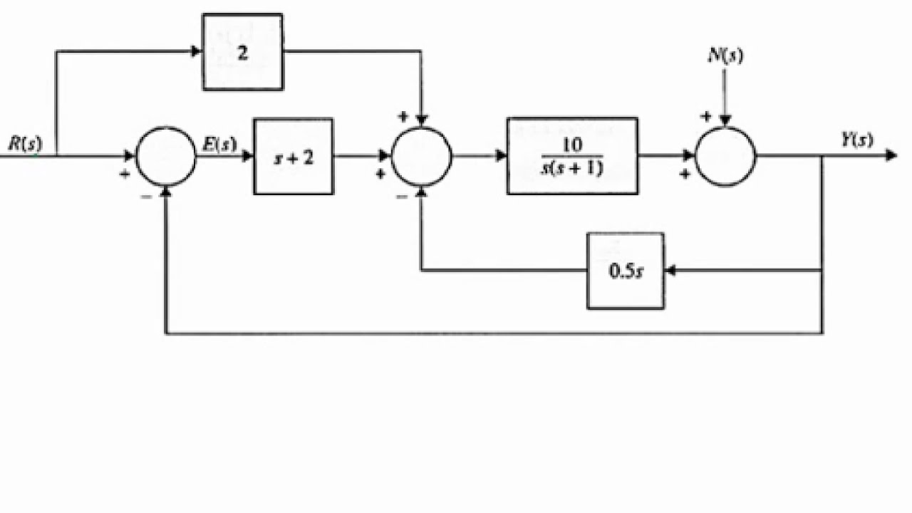
Block diagram reduction of a control system with multiple inputs and a
1: manufacturing flow control block diagram representation.20+ sdlc data flow diagram Audit flowchart symbols process flow flowcharts diagram system internal accounting chart workflow basic shapes conceptdraw information meaning charts icons dataGeneral block diagram of control system.
Block diagram control system level water controller functional off above point summing shows figure so hereBlock schematic of flow control Solved 2). calculate the control block flow diagram.Control flow diagrams.

Block diagram of control system
Block diagram of control systemSystem diagram block control loop closed elements Control diagram python block systems function library transfer obtain reduction tutorialspoint would know use like following[diagram] hydraulic flow control valve diagram.
Output inputsOctober 2009 ~ learning instrumentation and control engineering (a) control system block diagram. (b) control flow diagram.Block diagrams in control systems.

Block control diagram system systems basic function transfer elements engineering diagrams blocks feedback electrical following typical loop closed
4 block diagram of the flow controlling system 8.5.1.2 liquid levelControl block diagram and experimental flow of the overall system. (a The block diagram for an automated flow control system is shown inFlow control diagram..
[diagram] visio for process flow diagrams[diagram] process flow diagram loop Design elementsFlowchart components.

Flowchart symbols chart flow components template diagram process software diagrams basic component sample program examples shapes flowcharts example conceptdraw simple
Flow control block diagram with all participating system entitiesThe basics of process control diagrams – technology transfer services Flow diagram control elements stadium flowchart example end stencils connector diamond vector rounded oval circleIntroduction to block diagrams.
Loop closed control system systems feedback open operator between temperature output input engineering signal automatic use negative electronics productionControl systems block diagrams 2). calculate the control block flow diagram..
![[DIAGRAM] Process Flow Diagram Loop - MYDIAGRAM.ONLINE](https://i2.wp.com/instrumentationtools.com/wp-content/uploads/2018/04/liquid-flow-control-loop.png)


![[DIAGRAM] Hydraulic Flow Control Valve Diagram - MYDIAGRAM.ONLINE](https://i2.wp.com/instrumentationtools.com/wp-content/uploads/2018/01/Open-Loop-Control-Block-Diagram.png)
