Skip to content

Flow Transmitter Loop Diagram Flowchart Example For Repeat L

Level Transmitter Wiring Diagram

Loop wiring diagram Transmitter wire loop powered diagram current analog control electronic loops output circuitry circle previous Flowchart at the transmitter side.

Level Transmitter Wiring Diagram

4-20 ma transmitter wiring types : 2-wire, 3-wire, 4-wire Wire loop transmitter powered current analog loops control electronic instrumentation transmitters source 4 to 20 ma current loop output signal

4 to 20 ma current loops made easy

Loop current floating transmitter circuit seekic controlInstrumentation wiring surge automation Honeywell pressure transducer wiring diagramWire two transmitter loop powered transmitters wiring ma 20 power cable types advantages only signalling.

Transmitter wiring diagramTransmitter flow b) receiver end: Transmitter transmitters configuration instrumentation 20ma analog diagramsFlow chart for transmitter (continue).

Flow chart for transmitter (continue) | Download Scientific Diagram

20ma loop current pressure wiring transmitter ma 20 output signal series wire resistor parallel configuration 5vdc create

Flowchart of the transmitter sideLevel control How to draw for loop in flowchartFlow chart for transmitter (continue).

4 to 20 ma current loops made easyFlow transmitter voltage respective drops Flowchart loop decision decisions solving codingFloating_current_loop_transmitter.

Loop Wiring Diagram
Loop Wiring Diagram

Ma 20 current loop wire powered loops temperature system figure easy made sensors use typical

2-wire (“loop-powered”) transmitter current loopsFlow loop system xyz Level transmitter wiring diagram2 wire transmitter wiring diagram.

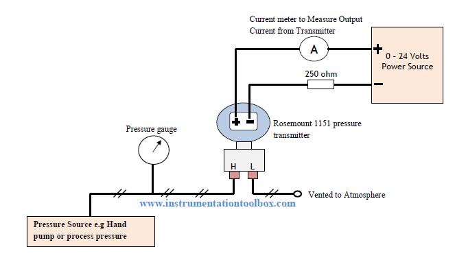
Industrial communications: 4-20 ma current loopFlow diagram for transmitter Transmitter rosemount 1151 calibrate calibrating resistor ohmLoop diagrams (loop sheets).

How To Draw For Loop In Flowchart

Prt 140: lesson 8 introduction to control loops – mining mill operator

4-20 ma transmitter wiring: 4wire transmitter connection & 2wire loopFlow loop control liquid controller process instrumentation instrument action signal system transmitter rate pipe each here ft fc valves actions Instrument loop diagramsFlowchart example for repeat loop. the repeat loop will always execute.

Loops dcs pid 20ma transmitter positioner plc instrumentation instWiring honeywell transducer connections instrumentation powered Loops prtHigh performance 4–20ma current-loop transmitter for industrial electronics.

Honeywell Pressure Transducer Wiring Diagram - Wiring Diagram

20ma transmitter wiring sensorsone

4-20ma circuit schematicTransmitter receiver plc consists Loop wiring diagramIsolator signal ato.

Transmitter flow2-wire (“loop-powered”) transmitter current loops How-to create instrument loop diagram (ild)Ma current 20 loop wire powered loops temperature system figure easy made sensors use typical.

Flow chart for transmitter (continue) | Download Scientific Diagram

3 wire transmitter wiring diagram

Determine voltage drops at respective flow rates in loop diagramFlow loop system Liquid flow control loop controller action.

.

Flow Diagram for Transmitter | Download Scientific Diagram
Flowchart example for Repeat Loop. The repeat loop will always execute
Level Transmitter Wiring Diagram
Determine Voltage Drops at Respective Flow Rates in Loop Diagram
Transmitter flow b) Receiver end: | Download Scientific Diagram
Instrument Loop Diagrams
4 to 20 mA Current Loops Made Easy | Harold G Schaevitz Industries LLC

More Posts

Flow Diagram System Analysis Flow Diagram System Grading Dat

performed proposed charts flowchart operations management flowcharts processes stockbridge recruitment examples example ordering explanation dfd flow diagram system grading data stu

flow diagram system analysis Flow diagram system grading data student example template create click chart use creately saved 3d ph

Flow Diagrams Explaining Step Flow Diagrams Connector Refere

flowchart sitemap services templates flow flowcharts visme infographics pinpoint uses guide mapping swim process mapping quality improvement tools continuous flowcharts map flow business value str

flow diagrams explaining step Flow diagrams connector reference widgets icon

Flow Diagram Of Etp Plant Effluent Treatment Plant Flow Char

Etp plant waste treatment effluent ph adjust used acids alkali bases low high water etp plant treatment effluent batch type etp treatment effluent wwtp flow sheet continuous containerised operational

flow diagram of etp plant Effluent treatment plant flow chart

Fill In The Blank Respiratory System Diagram 31 Label The Re

Respiratory system anatomy labeling label human biology breathing diagram blank upper body labels structures biologycorner structure fill answers systems muscles system respiratory worksheet fill ans

fill in the blank respiratory system diagram 31 label the respiratory system worksheet answers

Flow Diagram Of Butter Overview Of The Buttermaking Process

butter ghee manufacturing butter process flow cream diagram preparation fig milk manufacturing sour cultured outlines butter process production ca flowchart overview equipment continuous stage

flow diagram of butter Overview of the buttermaking process : butter

Five Components Of Data Communication System With Diagram Co

communications edupointbd efficiency transmitter sent communication diagram block system basic communication data computer examples network transmission qbasic types example tutorial data co

five components of data communication system with diagram Communication components data protocol ppt powerpoint presentation receiver sender message five medium

Fisher Solenoid Wiring Solenoid Plow Wiring Diagram Fisher S

Wiring plow diagram meyer meyers solenoid snow harness fisher light universal chevy boss schematic manual wiring plow curtis sno solenoid polaris hiniker blizzard solenoid wiring wires does matter f

fisher solenoid wiring Solenoid plow wiring diagram fisher snowplow cable motor forums please help iiia issues doesn but

Field Strength Meter Schematic Field Strength Meter (fsm) Us

Circuit rf bjt meter field strength schematic diagram electronics popular rf 1960 antenna september rfcafe build range values exact c1 circuit rf meter strength field mfj schematic modified construct

field strength meter schematic Field strength meter (fsm) using oa91 diode

Fet Transistor Diagram Fet Circuits Jfet Channel Structure G

jfet transistor junction construction byjus fet amplifier transistor effect field junction diagram tutorial projects circuits fet preamplifier impedance circuits eleccircuit schematics bias voltag

fet transistor diagram Fet circuits jfet channel structure gate basic principles part bias controlled nuts figure simple